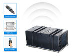


The overall structure of the automotive CAN bus
The CAN bus consists of a CAN controller, a CAN transceiver, a data transmission line, a data transmission terminal, etc. The ECU (engine control unit), TCU (transmission control unit), FEPS (keyless entry and keyless start system), and the instrument cluster of the CB311 are connected through the CAN bus. The CAN controller and CAN transceiver are integrated in the electronic control unit.
The overall structure of the CAN bus mainly includes the following key components:
1. CAN controller
As a core component, the CAN controller is located inside the electronic control unit. Its responsibility is to receive data sent by the control unit microprocessor and perform necessary processing. Subsequently, it will pass the processed data to the CAN transceiver. Similarly, the CAN controller can also receive data from the transceiver, further process it, and then transmit it back to the control unit microprocessor.
2. CAN transceiver
The CAN transceiver is also integrated in the electronic control unit and has the functions of receiving, sending and converting data signals. It converts the level signal data from the CAN controller into a voltage signal and sends it out in the form of broadcasting through the data transmission line. At the same time, it can also receive the voltage signal from the data transmission line, convert it into level signal data, and then send it to the CAN controller.
3. Data transmission line
The data transmission line is an important part of the CAN bus. It adopts a twisted pair design to reduce interference. This twisted pair has a specific twist pitch and cross-sectional area, usually referred to as CAN-high line (CAN-H) and CAN-low line (CAN-L). The data transmitted on these two lines is the same, but the voltage values are mirrored to keep the voltage difference constant. This design can effectively offset the electromagnetic field effect, thereby preventing interference from external radiation and maintaining neutrality when radiating outward.
4. Data transmission terminal
The data transmission terminal is a resistor, whose main function is to prevent data from being reflected back at the end of transmission, thereby avoiding data damage. Usually, the resistance value of the data transmission terminal is 120Ω. In CB311, the data transmission terminal consists of two 120Ω resistors, which are integrated in the BCU and the instrument cluster respectively.
In summary, the overall structure of the CAN bus realizes efficient and reliable data transmission through the coordinated work of components such as the CAN controller, CAN transceiver, data transmission line, and data transmission terminal, providing strong support for the communication between the electronic control units inside the car.